Symbol For Motor In Circuit Diagram / Learn.Digilentinc | Light Tracking Servo - Dpdt = double pole, double throw.. The figure shows the circuit diagram of two stage stepper motor driver. A circuit diagram can be defined as a graphical representation of an electronic circuit. Circuit diagrams can be created with thousands of possible shapes and icons and lucidchart's. A circuit diagram (electrical diagram, elementary diagram, electronic schematic) is a graphical representation of an electrical circuit. Designation of components in the wiring diagram.
Both line and wiring diagrams are a language of pictures. Should have a fuse on control circuit and possibly show a transformer for control circuit in which more often than not one is used. Electrical circuit symbols on chalkboard. Without microphone we can't think electronics. A circuit diagram (electrical diagram, elementary diagram, electronic schematic) is a graphical representation of an electrical circuit.
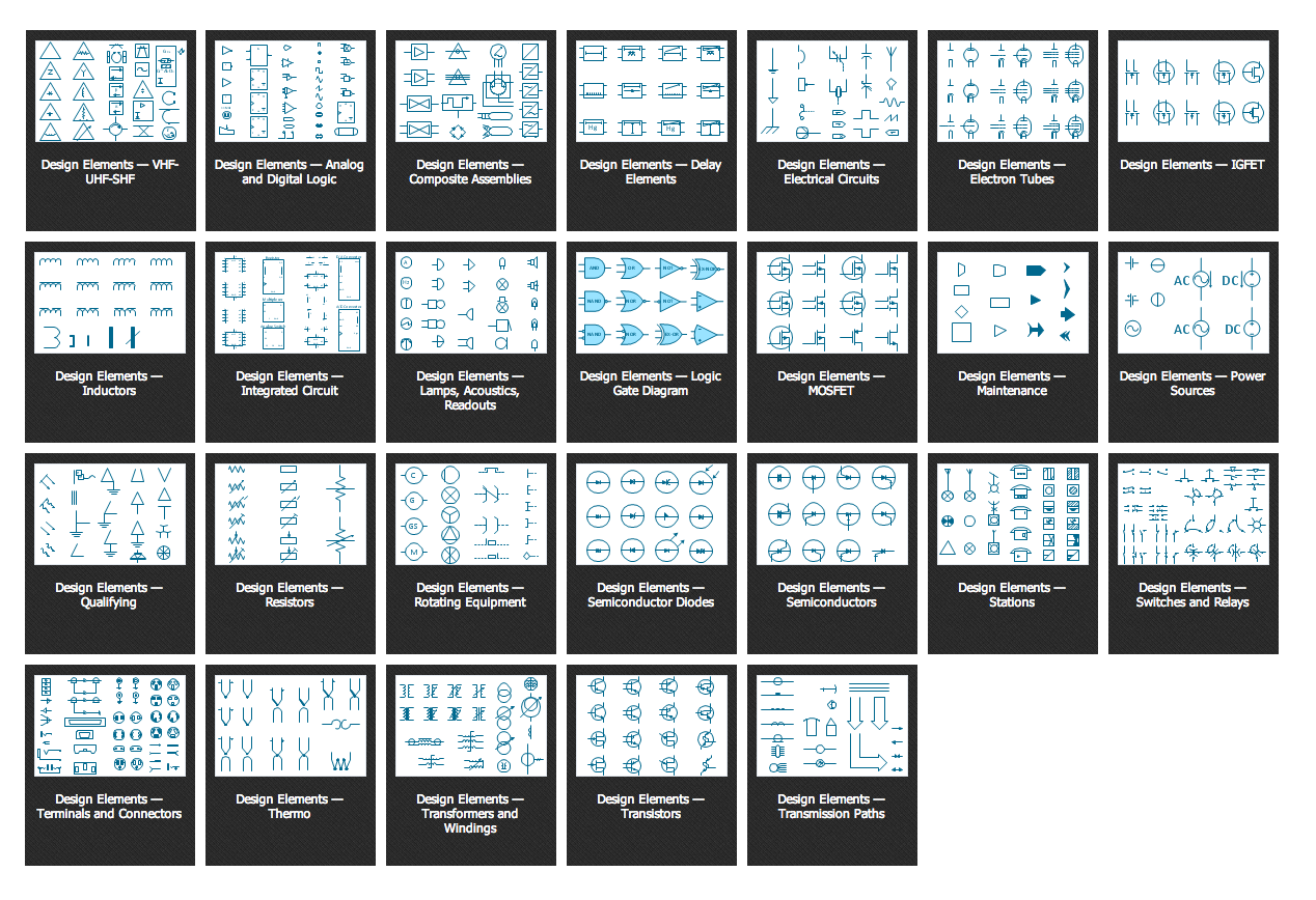
Electrical Symbols | Terminals and Connectors from www.conceptdraw.com Do we use a motor symbol when wanting to show a fan? Electrical symbols and electronic circuit symbols are used for drawing schematic diagram. Designation of components in the wiring diagram. This enables anyone to read a circuit diagram and know what it. Should have a fuse on control circuit and possibly show a transformer for control circuit in which more often than not one is used. A family of graphic symbols has been developed to represent fluid power components and systems on schematic drawings. The symbols represent electrical and electronic components. This is a symple microphone circuit diagram.
Standardized symbols make diagrams easier to read.
It is not difficult to learn the basic symbols. Circuit or schematic diagrams consist of symbols representing physical components and lines representing wires or electrical conductors. This diagram includes different electronic components with standardized representations of symbols when a symbolic circuit uses simple component images. To build a circuit you need a different diagram showing the layout of the parts on stripboard or printed circuit board. It is important to understand who will be viewing the circuit diagram to ensure use of the correct types of symbols. Both line and wiring diagrams are a language of pictures. In the event lines cross, use line hops to show wire crossover. The actual layout of the components is usually quite different from the circuit diagram. Circuit symbols overview resistors capacitors inductors, coils, chokes & transformers diodes bipolar transistors field today, circuit symbols and their usage has been pretty much standardised. This enables anyone to read a circuit diagram and know what it. Instantaneous braking of dc motors schematic circuit diagram. Without microphone we can't think electronics. These electrical and electronics circuit symbols are used in circuit diagrams to explain how a circuit is interconnected.
Circuit symbols are used in circuit diagrams which show how a circuit is connected together. In the event lines cross, use line hops to show wire crossover. Notes) symbol denotes dc chassis ground. The symbols represent electrical and electronic components. Circuit symbols are used in circuit schematic diagrams which show how a circuit is connected together electrically.
Using L298n H Bridge with Stepper Motors on Arduino ... from www.14core.com This is a symple microphone circuit diagram. Circuit symbols and circuit diagrams. Should have a fuse on control circuit and possibly show a transformer for control circuit in which more often than not one is used. In the united states, the american national standards institute (ansi) is responsible for symbol information. This physics video tutorial explains how to read a schematic diagram by knowing what each electric symbol represent in a typical electrical circuit. The actual layout of the components is usually quite different from the circuit diagram. These electrical and electronics circuit symbols are used in circuit diagrams to explain how a circuit is interconnected. A final means of describing an electric circuit is by use of conventional circuit symbols to provide a schematic diagram of the circuit and its components.
Remote control circuit with optocoupler schematic circuit diagram.
Circuit symbols are used in circuit diagrams (schematics) to represent electronic components. The symbols for different electronic devices are shown below. Ciircuits, diagrams & symbols includes: Do we use a motor symbol when wanting to show a fan? These electrical and electronics circuit symbols are used in circuit diagrams to explain how a circuit is interconnected. The original layout of electronic components to build an actual electronic circuit we need different diagram showing the layout of the parts on printed circuit board ( pcb ). In order to learn how to read a circuit diagram, it is necessary to learn what the schematic symbol of a component looks like. Both line and wiring diagrams are a language of pictures. Circuit symbols are used in circuit schematic diagrams which show how a circuit is connected together electrically. These outputs are fed to transistor to drive the stepper motor in orderly way. All circuit symbols are in standard format and can be used for drawing schematic circuit diagram and layout. This switch can be wired up as a reversing switch for a motor. Click on each link given below to view the the wire is coiled on a soft iron core.
Without microphone we can't think electronics. This enables anyone to read a circuit diagram and know what it. Should have a fuse on control circuit and possibly show a transformer for control circuit in which more often than not one is used. So, essentially the question is, what symbol to use to specify a fan in an electronic circuit? We need this circuit diagram in every where in the electrinics.
PLC application for reduced voltage-start motor control from electrical-engineering-portal.com In order to learn how to read a circuit diagram, it is necessary to learn what the schematic symbol of a component looks like. Notes) symbol denotes dc chassis ground. • explain the role of a snubber diode • describe how pwm controls dc motor speed • implement a transistor circuit and arduino program for. Circuit or schematic diagrams consist of symbols representing physical components and lines representing wires or electrical conductors. Circuit symbols and circuit diagrams. Ciircuits, diagrams & symbols includes: It is important to understand who will be viewing the circuit diagram to ensure use of the correct types of symbols. In the united states, the american national standards institute (ansi) is responsible for symbol information.
This switch can be wired up as a reversing switch for a motor.
It is not difficult to learn the basic symbols. Circuit symbols overview resistors capacitors inductors, coils, chokes & transformers diodes bipolar transistors field today, circuit symbols and their usage has been pretty much standardised. The symbols for different electronic devices are shown below. Low voltage release and low voltage protection are the basic control circuits encountered in motor control applications. Really this is a block diagram symbol because it represents a circuit rather than just one component. Instantaneous braking of dc motors schematic circuit diagram. In conjunction with circuit diagram symbols, there are also a series of different types of line styles to connect objects. The symbols represent electrical and electronic components. Without microphone we can't think electronics. These electrical and electronics circuit symbols are used in circuit diagrams to explain how a circuit is interconnected. In the event lines cross, use line hops to show wire crossover. Both line and wiring diagrams are a language of pictures. This is a symple microphone circuit diagram.